CATVアンプ

HOME

CATVアンプ

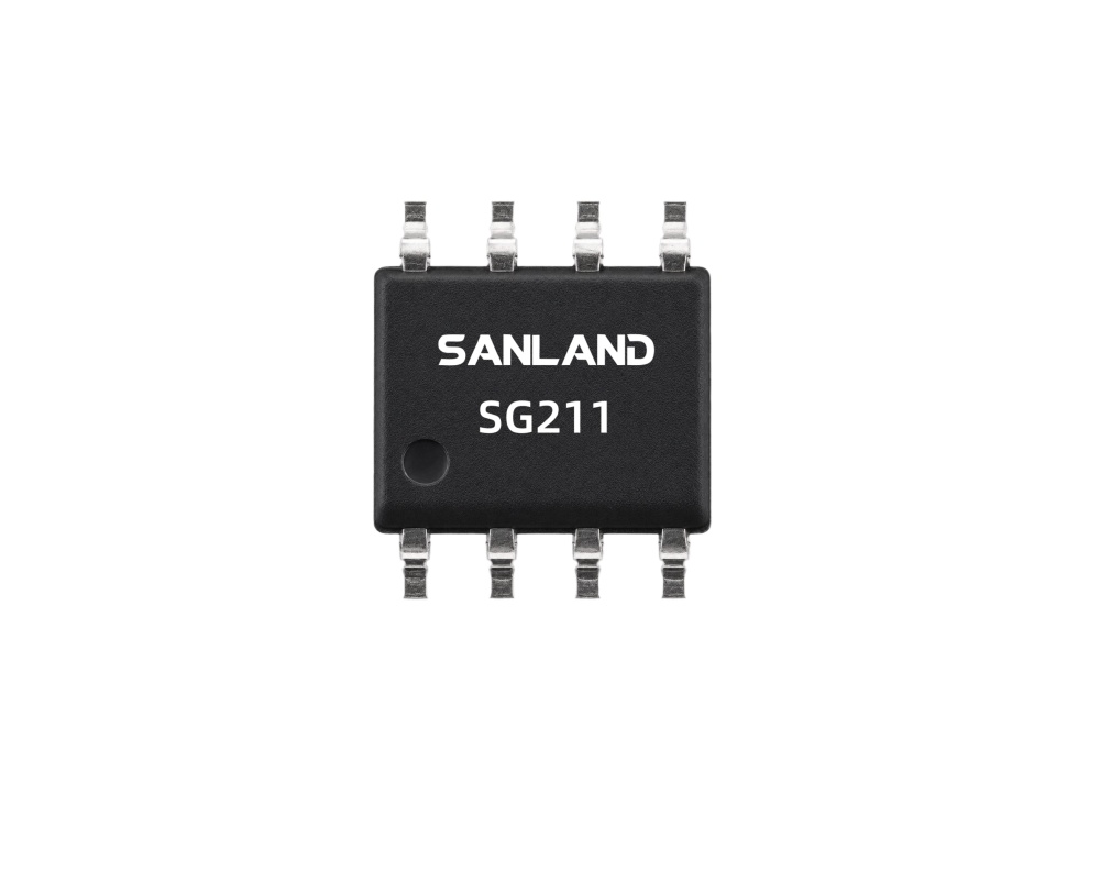
SG211 5–700 MHz Balanced Return Path Amplifier

SG211 5–700 MHz Balanced Return Path Amplifier for DOCSIS 4.0 Applications

SG211 5–700 MHz Balanced Return Path Amplifier

Key Features

●  5 MHz to 700 MHz Operation
●  27 dB Typical Gain
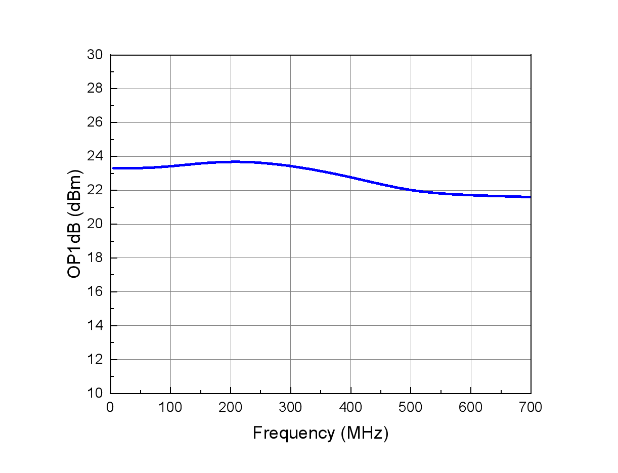
●  +23 dBm P1dB
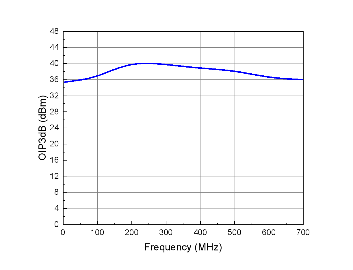
●  +38 dBm OIP3
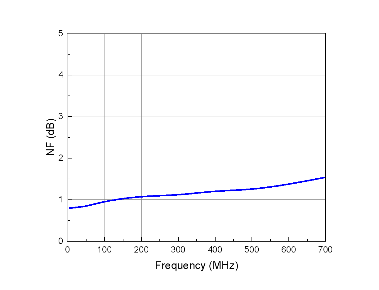
●  Noise Figure: 1.5dB @700MHz
●  5 V / 75 Ω Balanced Design
●  RoHS Compliant


SG211 is a GaAs pHEMT balanced RF amplifier designed for 5–700 MHz return-path and upstream applications. Operating from a single 5 V supply, it combines 27 dB typical gain, low noise and high output linearity for DOCSIS 4.0 optical nodes, amplifiers and CMTS-related equipment.

The differential RF architecture and 75 Ω system interface make SG211 suitable for broadband CATV upstream signal chains where low noise, high gain and linear output performance are required.

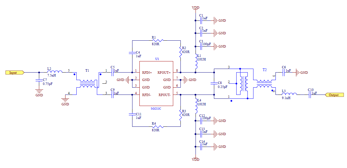
Reference Application Circuit

SG211 5–700 MHz balanced return path amplifier reference application circuit

■ Pin Assignment & Package

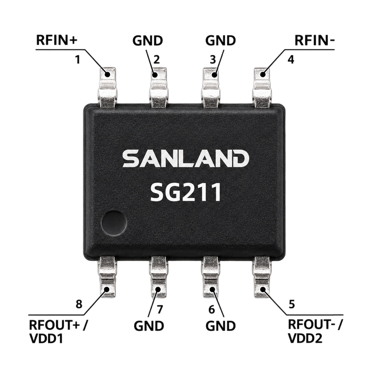
SG211 5–700 MHz balanced return path amplifier 8-pin SOIC pin assignment
Pin Name Function
1 RFIN+ RF Input +
4 RFIN− RF Input −
5 RFOUT− / VDD2 RF output − and VDD through RF choke
8 RFOUT+ / VDD1 RF output + and VDD through RF choke
2, 3, 6, 7 GND Ground

Body Size: 5.0 × 4.0 × 1.52 mm Max.

The compact 8-pin SOIC package makes SG211 suitable for broadband CATV return-path and upstream amplifier designs where PCB space and thermal performance are important.

CATV return-path amplifier evaluation

Evaluating an Alternative Return Path Amplifier?

SG211 is a 5 V, 8-pin SOIC balanced RF amplifier covering 5–700 MHz. It can be considered for engineering evaluation in selected CATV return-path and upstream amplifier designs. Frequency range, gain, noise figure, output linearity, balanced RF architecture and existing bias circuitry should be reviewed for the intended application.

5–700 MHz 5 V supply 8-Pin SOIC 27 dB gain

Qorvo reference part

QPB8896

5–700 MHz Balanced Return Path Amplifier


QPB8896 and SG211 are both 5 V balanced RF amplifiers covering 5–700 MHz for CATV return-path and upstream applications. QPB8896 provides 25 dB typical gain, while SG211 provides 27 dB typical gain, with similar P1dB and OIP3 performance.

Gain & current: SG211 provides approximately 2 dB higher typical gain while operating at a slightly lower typical current.

MACOM reference part

MAAM-011163

5–1218 MHz Differential CATV Amplifier


MAAM-011163 and SG211 are both 5 V differential amplifiers for 75 Ω CATV signal chains, with balanced RF input and output architecture. SG211 provides 27 dB typical gain compared with 19 dB for MAAM-011163 and is optimized for the 5–700 MHz return path.

Gain comparison: SG211 provides substantially higher typical gain for 5–700 MHz return-path applications.

Analog Devices reference part

ADCA5191

5 MHz–1.8 GHz Broadband CATV Amplifier


ADCA5191 and SG211 can both serve as CATV upstream amplification stages across the 5–700 MHz return path. SG211 provides 27 dB typical gain from a fixed 5 V supply and uses a compact 8-pin SOIC package, while ADCA5191 uses a wider-band, adjustable-bias architecture.

Implementation comparison: SG211 uses a simpler fixed 5 V supply and compact 8-pin SOIC package for 5–700 MHz upstream designs.

MACOM reference part

MAAM-011185

5–300 MHz CATV Return Path Differential Amplifier


MAAM-011185 and SG211 are both 5 V differential amplifiers designed for CATV return-path applications. SG211 extends the operating range from 300 MHz to 700 MHz and provides 27 dB typical gain compared with 21.2 dB for MAAM-011185.

Frequency coverage: SG211 extends return-path operation from 300 MHz to 700 MHz while providing higher typical gain.

Published specifications for reference parts may use different test frequencies, bias conditions and evaluation circuits. Compare devices at the same frequencies and circuit conditions before qualification.

Critical check: pin configuration and bias network

Cross-reference information is provided for evaluation purposes. Electrical characteristics, pin configuration, balanced input/output arrangement, RF choke bias network, package and PCB compatibility should be verified for each application. SG211 should not be described as a drop-in or pin-to-pin replacement unless circuit-level compatibility has been independently confirmed.

What to verify in your design

RF performance Gain, NF, OP1dB, OIP3 and return loss across the operating band.
Circuit and supply Pin assignment, output bias, RF chokes, transformers, current budget and thermal margin.
Sourcing needs Qualification timeline, sample quantity and estimated annual demand.

Request a cross-reference review

Send your original part number, frequency range, target gain/NF, OP1dB/OIP3 requirements, schematic or BOM (if available), and annual quantity to the SANLAND engineering team.

Request a Cross-Reference Review

Frequently Asked Questions

What is the frequency range of SG211?

SG211 operates from 5 MHz to 700 MHz and is designed for 75 Ω return-path and upstream RF applications.

What are the typical gain and linearity of SG211?

At +5 V, SG211 typically provides 27 dB gain, +23 dBm OP1dB and +38 dBm OIP3.

Is SG211 designed for DOCSIS 4.0 return-path applications?

Yes. SG211 is designed as a balanced return-path amplifier for applications including CMTS equipment, return-path optical receivers, full-duplex upstream, DOCSIS 4.0 optical nodes and amplifiers.

Can SG211 be evaluated as an alternative to QPB8896, MAAM-011163, ADCA5191 or MAAM-011185?

Yes. SG211 can be evaluated as an alternative for selected broadband CATV return-path and upstream amplifier designs. Frequency range, gain, linearity, noise figure, pin configuration, bias network and PCB compatibility should be verified before replacement.

What applications is SG211 designed for?

SG211 is intended for return-path optical receivers, CMTS equipment, full-duplex upstream, DOCSIS 4.0 optical nodes and CATV amplifiers.

Does SG211 use a balanced RF architecture?

Yes. SG211 provides differential RF input and output connections through RFIN+/RFIN− and RFOUT+/RFOUT−.

01
SG211 / RF PERFORMANCE

Typical RF Performance

Parameter Typical
Frequency 5–700 MHz
Supply Voltage 5 V
Supply Current 256 mA
Gain 27 dB
Gain Slope 1 dB
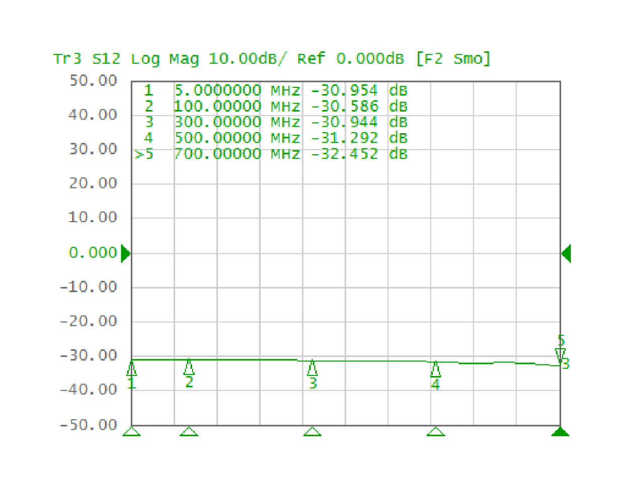
Reverse Isolation 31 dB
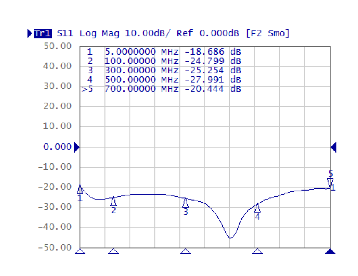
Input Return Loss 20 dB
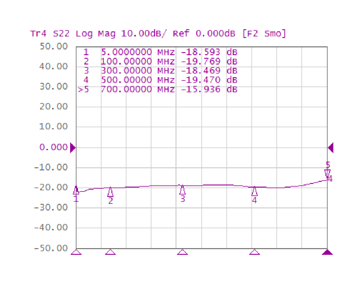
Output Return Loss 19 dB
Noise Figure 1.1 dB
OIP2L 62 dBm
OIP2U 65 dBm
OIP3 38 dBm
OP1dB 23 dBm
Thermal Resistance 57 °C/W
TEST BASIS

Typical values are specified at TEMP = +25°C, VDD = +5 V in a 75 Ω system, full band unless otherwise noted. OIP2 uses 6 MHz tone spacing at +5 dBm output per tone; OIP3 uses 1 MHz tone spacing at +5 dBm output per tone.


02
SG211 / MEASURED CURVES

Typical Performance Curves

RF CHARACTERISTICS
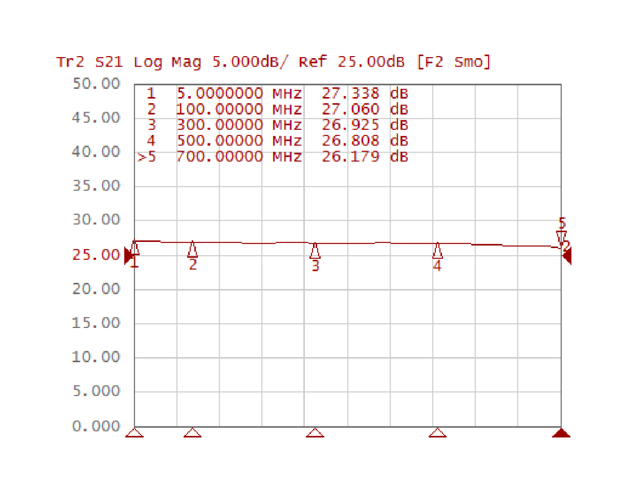
01 S21 / Gain Forward gain
SG211 S21 gain vs frequency from 5 MHz to 700 MHz
02 S11 / Input Return Loss Input matching
SG211 S11 input return loss vs frequency from 5 MHz to 700 MHz
03 S22 / Output Return Loss Output matching
SG211 S22 output return loss vs frequency from 5 MHz to 700 MHz
04 S12 / Reverse Isolation Reverse isolation
SG211 S12 reverse isolation vs frequency from 5 MHz to 700 MHz
LINEARITY & NOISE
05 Noise Figure Noise response
SG211 noise figure vs frequency from 5 MHz to 700 MHz at 5 V
06 Output P1dB Output compression
SG211 output P1dB vs frequency from 5 MHz to 700 MHz at 5 V
07 OIP3 Linearity response
SG211 OIP3 vs frequency from 5 MHz to 700 MHz at 5 V
Headend and CMTS equipment for broadband upstream CATV amplification

Headend & CMTS Equipment

Broadband upstream amplification for CATV headend and CMTS signal chains.

HeadendCMTSUpstream
Return path optical receiver post-amplification for upstream RF output

Return Path Optical Receivers

Post-amplification for upstream RF outputs from return-path optical receivers.

Optical RXReturn PathUpstream RF
Full duplex upstream RF path amplification

Full Duplex Upstream

Low-noise, high-linearity amplification for full-duplex upstream RF paths.

FDXLow NoiseHigh Linearity
DOCSIS 4.0 optical node and CATV amplifier return path amplification

DOCSIS 4.0 Nodes & Amplifiers

5–700 MHz return-path amplification for DOCSIS 4.0 optical nodes and CATV amplifiers.

5–700 MHzDOCSIS 4.0CATV

メッセージを送る

メッセージを送る
弊社製品にご興味がおありの方、詳細を知りたい方は、ここにメッセージを書いて[送信]ボタンを押してください。できるだけ早くお返事いたします。
送信

HOME

製品

whatsApp

コンタクト